Hello, This project is about Hamming code (7,4) Encoder with serial input and Decoder using Verilog HDL.
- Menna Ahmed Heshmat. ( Github: https://github.com/mennaaheshmat )
- Nadine Ashraf Adeeb.
- Tasneem Yassin Mostafa.
- Sara Gouda Rohaim.
- Tasnim Ragab Abdelhamid. ( Github: https://github.com/tasnimragab )
Data word is applied as an input in the encoder circuit which performs XOR operations on the given data word and Thus the required parity bits are generated from the parity generator. Parity bits and data bits together form the Code word. An encoder circuit of hamming code for 4 bit data word as shown in figure. Following this circuit pattern we can design an encoder of hamming code for 7 bit data word And realized it by means of tanner EDA tools.
1. Serial-to-Parallel Converter
A serial to parallel converter is a digital circuit where we feed the input data serially, and read the outputs in parallel. A 4-bit serial-to-parallel shift register is one of the simplest types of circuits utilizing four D-type flip-flops.

2. Operation
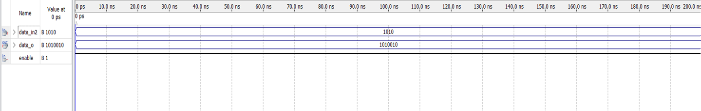
The output of operation consists of 4-bits and 3-parity bits. We calculate the parity bits by P0 = XOR{data_in[0], data_in[1], data_in[2]}
P1 = XOR{data_in[0],data_in[2],data_in[3]}
P2 = XOR{data_in[1],data_in[2],data_in[3]}
data _out = { data_in[3], data_in[2], data_in[1], P2, data_in[0], P1, P0}.
3. Counter
We enter bits from 0 to 3. When it reaches to bit number 3 it goes to execute the operation and then complete the rest of the cycle.


Code word is applied as input. Then check bits are generated by the checker bit generator to check The parity bits. These check bits locates the error in the code word by means of decoder circuit.
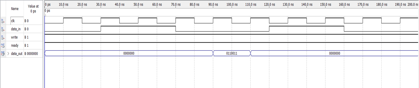
1. Operation The inputs of the operation is the 7-bits that comes from encoder and the output is 4-bits which is essential and remove the 3-bits of the parity.

2. Parallel-to- Serial Converter
A parallel to serial converter is a digital circuit where we feed the input data in parallel way , and read the outputs in series.

3. Counter
We have internal register called count when the count<=3 the shift will be equal 1. And when the count==4 the shift will be equal 0.


Clock Divider: In our design, we didn’t use the clock divider because we used serial-to-parallel encoder and parallel-to-serial decoder. But if we use in encoder another stage parallel _to_serial after operation stage and another stage in decoder which is serial _to _parallel before the operation of the decoder. The clock divider will be connected with the stages that we added. Furthermore, it can control the speed of input and output.